All Activity
- Yesterday
-

Need to know some info about replacing the strut cartridge?
89-W-Body-Regal replied to 89-W-Body-Regal's topic in Brakes/Suspension/Steering/Wheels/Tires
I will remember not to use the impact on the new ones and use the socket. I will have to torque to specs anyhow the nut on top. I try to use the Torx and socket on the old struts but it was so dirty I wouldn’t come loose and stripped the thread. So I used an impact to remove the nut. - Last week
-
 Mike1998Lumina joined the community
 -
Brake Line Size
Mike1998Lumina replied to mediabandit's topic in Brakes/Suspension/Steering/Wheels/Tires
Hi, replacing my sons 1998 Lumina with a little over 250,000 miles on it rear brake lines found some 25' 3/16 kits with fittings online I have a line bender and cutter and a flare kit ,, replacing rear lines this weekend hoping its 3/16 as posted. I'd get rid of it but that 3.1 just runs like a top and the trans is still smooth. I've rebuilt all four corners and a handful of other items over the years but its a former grandparent car so it was well maintained and we have done the same. This series of 3.1 3.8 V6 chevy cars was almost bullet proof I still see a ton of Luminas, Monte Carlos, Corsica's on the road and setting on driveways. -
Need to know some info about replacing the strut cartridge?
55trucker replied to 89-W-Body-Regal's topic in Brakes/Suspension/Steering/Wheels/Tires
The #50 torx tip is needed to stop the piston shaft from rotating in the shock housing while undoing & tightening up the the retaining nut. As I stated earlier some aftermarket shocks no longer make use of a torx design for the socket interface at the top end of the piston shaft. Spinning the piston shaft with an impact gun is not desirable. Doing so with the outgoing shock is alright but no so with the new shock. -
Need to know some info about replacing the strut cartridge?
ron350 replied to 89-W-Body-Regal's topic in Brakes/Suspension/Steering/Wheels/Tires
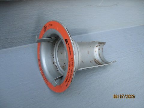
Then you are looking for an OTC 7568A kit. Where are you going to find just the tool you need? -
Need to know some info about replacing the strut cartridge?
89-W-Body-Regal replied to 89-W-Body-Regal's topic in Brakes/Suspension/Steering/Wheels/Tires
So seeing the photos you posted that’s all I need those tools? I wouldn’t need the whole kit. -
Need to know some info about replacing the strut cartridge?
89-W-Body-Regal replied to 89-W-Body-Regal's topic in Brakes/Suspension/Steering/Wheels/Tires
It would be cheaper I think just to get the tools I need. I don’t really need the Torx socket or that other socket it goes with it because I can remove the nut with an impact and I have that long strut spreader cylinder tool. -
Need to know some info about replacing the strut cartridge?
ron350 replied to 89-W-Body-Regal's topic in Brakes/Suspension/Steering/Wheels/Tires
The strut kit i have says OEM # 27034. This is the same kit that Autozone used to rent. I see ebay has the same kit listed as T&E Tools AT185. -
Need to know some info about replacing the strut cartridge?
89-W-Body-Regal replied to 89-W-Body-Regal's topic in Brakes/Suspension/Steering/Wheels/Tires
Which kit is this? Any brand names I can buy with everything I need? One kit i bought was kent moore that was originally used by GM Dealers when these cars were new. The tool service kit was missing tools so I had to buy some tools extra that weren't in the kit. When I didn't have luck removing the strut cartridges I sent it back. -
Need to know some info about replacing the strut cartridge?
89-W-Body-Regal replied to 89-W-Body-Regal's topic in Brakes/Suspension/Steering/Wheels/Tires
Which kit was that in and is that the nut from the cartridge that long tool fits over? -
Need to know some info about replacing the strut cartridge?
89-W-Body-Regal replied to 89-W-Body-Regal's topic in Brakes/Suspension/Steering/Wheels/Tires
I have this exact tool I bought off ebay with the nuts that tighten this down. Mine didn't fit because it was too tight. But you need to move the strut a little to the sides so this can fit down the strut tower ? -
Need to know some info about replacing the strut cartridge?
89-W-Body-Regal replied to 89-W-Body-Regal's topic in Brakes/Suspension/Steering/Wheels/Tires
Yes! that is the tool I was able to use as well. But I couldn't seem to fit the spanner nut down the strut tower hole because I didn't have any clearance to fit the nut socket in there. -
I don't remember having any shift interlock issues when my turn signal switch was bad...but I don't usually put it into gear less than a few seconds after startup and that was about 7 years ago.
-
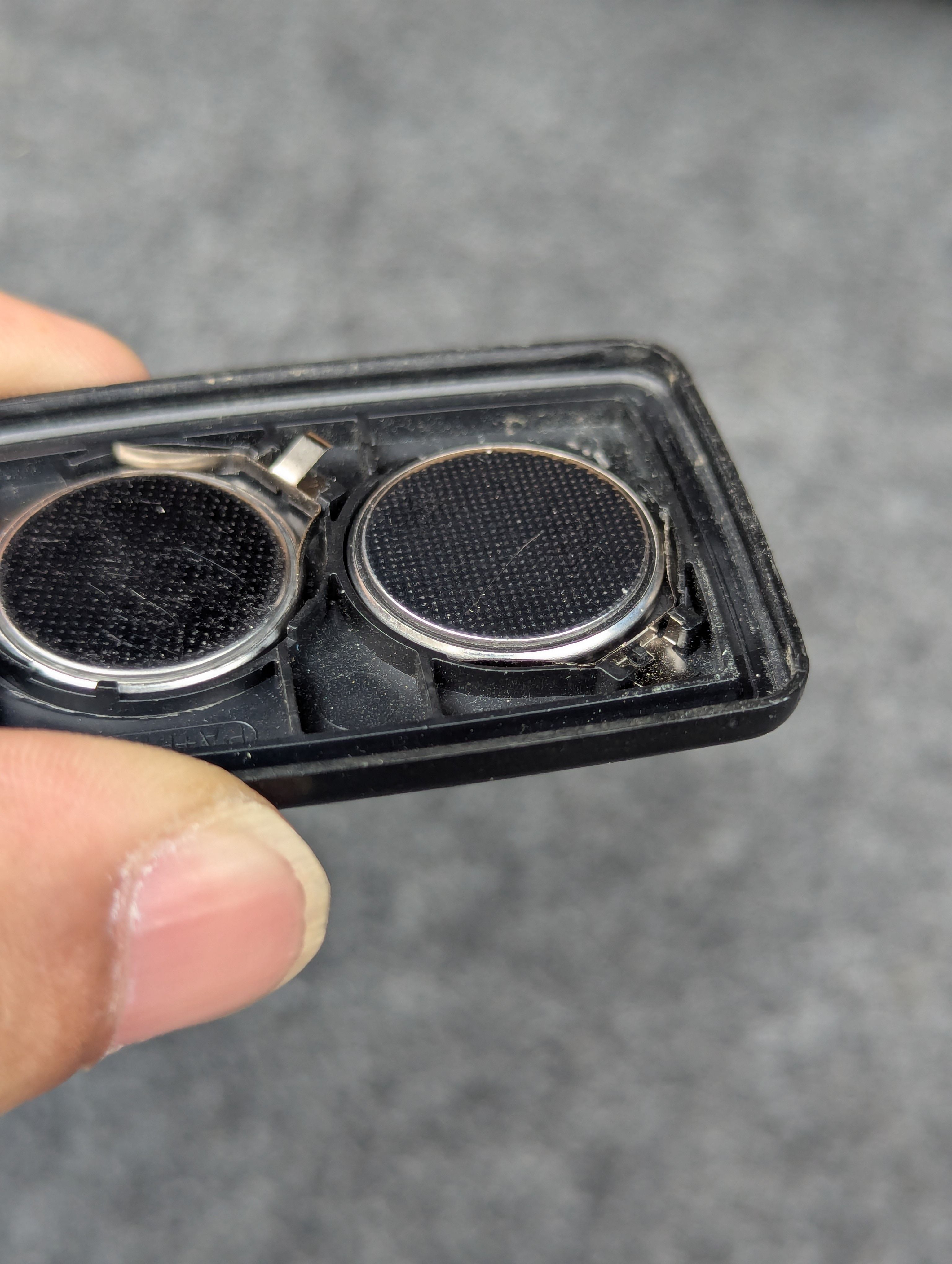
I noticed the metal tab was depressed on one of the batteries. Tab broke off as soon as I gently tried to pry it back upwards. Tab was barely hanging on. Does anyone know if these batteries run in parallel or series? If series then maybe this could the issue.
-
Locks cycling just means part of the receiver is okay. Doesn't necessarily mean it's receiving a signal correctly. I've had bad ones do that too. Although it's definitely easier to rule it in or out with multiple fobs.
-
Can't seem to reprogram my current fob. When in programming mode clicking any buttons on the fob do nothing. I'm definitely in programming mode because they locks activate when ground the b/w wires. New tested batteries in fob and the circuits look clean. Thoughts?
-
I grounded the black and white cable in the the trunk and the locks switched on and off so reciever is okay. Should have started with this test but learned something from ripping up the car. Now to figure if it's my fob or just gotta be programmed. Anyone have success with third party fobs?
-
Corkscrew joined the community
-
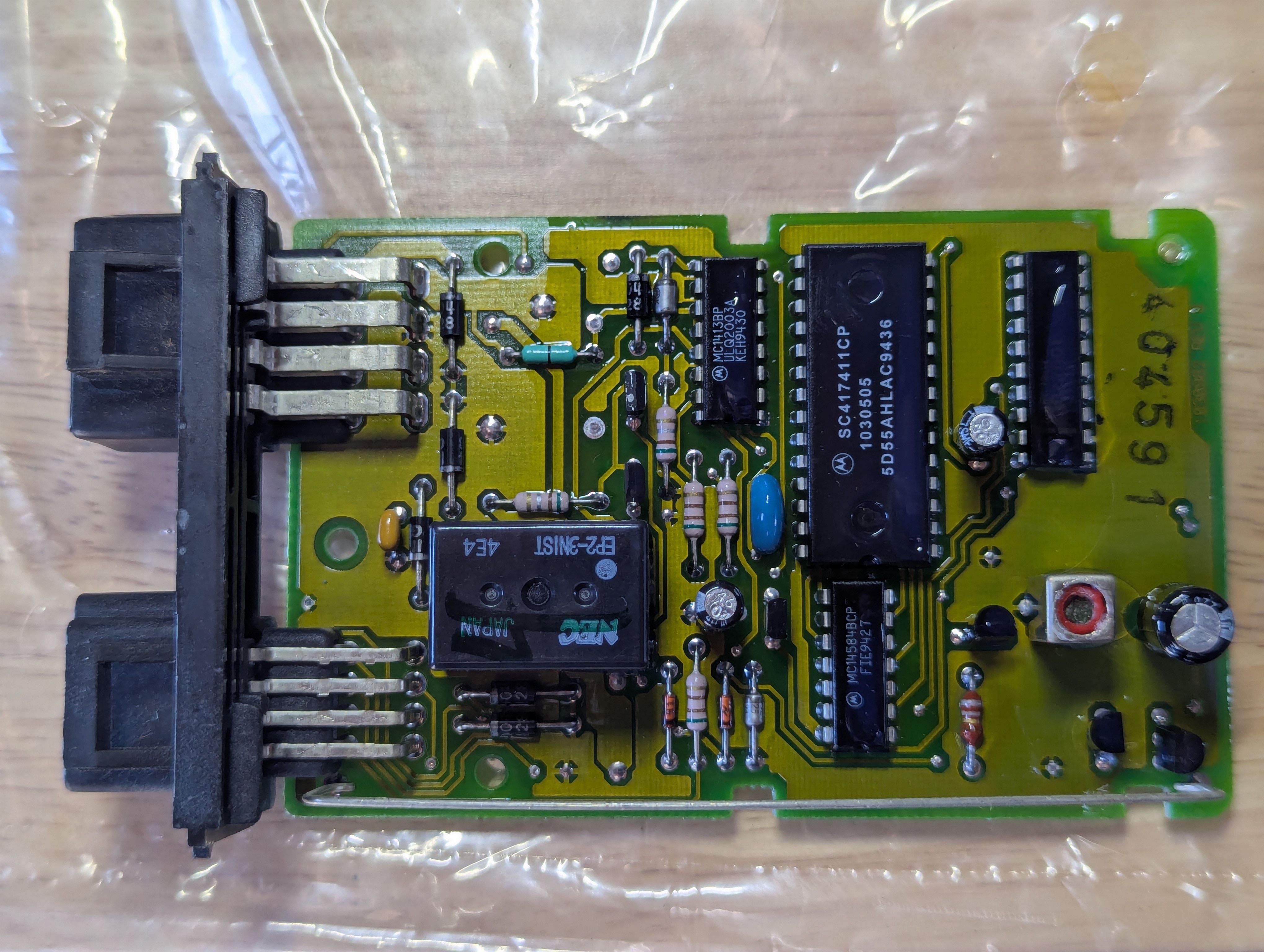
I've never been able to SEE the bad solder joints, and I think the glossy conformal coating would probably hide them if there were some. I've always just cleaned off the coating and resoldered the joints anyway. That's always worked. I think most people who have done it had the same experience.
-
The board looks pretty clean...can't see any damage at all and starting to doubt its this issue...?
-
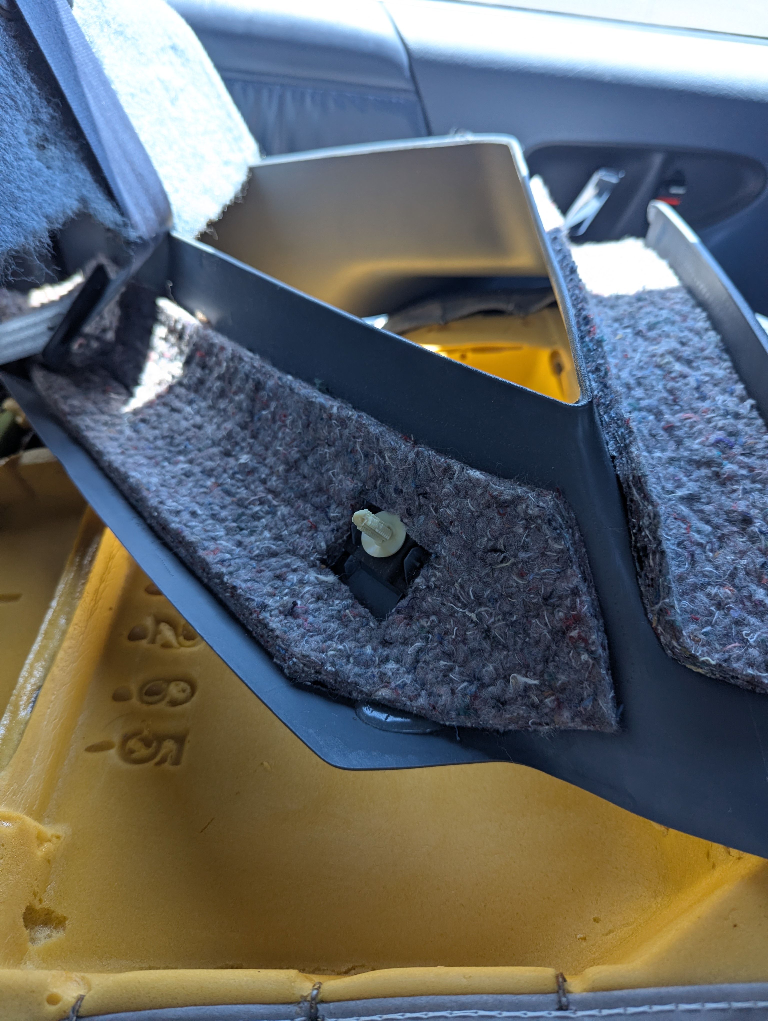
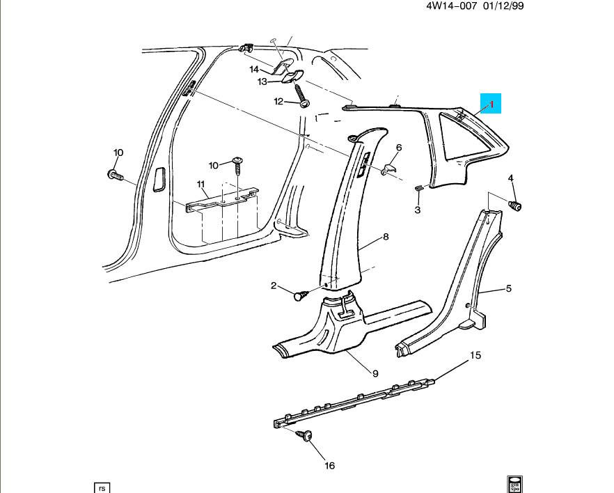
Thanks that diagram helps. Got my neighbor to help. Putting these photos up for anyone else that finds this thread. Two red clips at the top of door, one white xmas tree clip, and a clip on the inside of the car that requires you pull the panel forward to release.
-
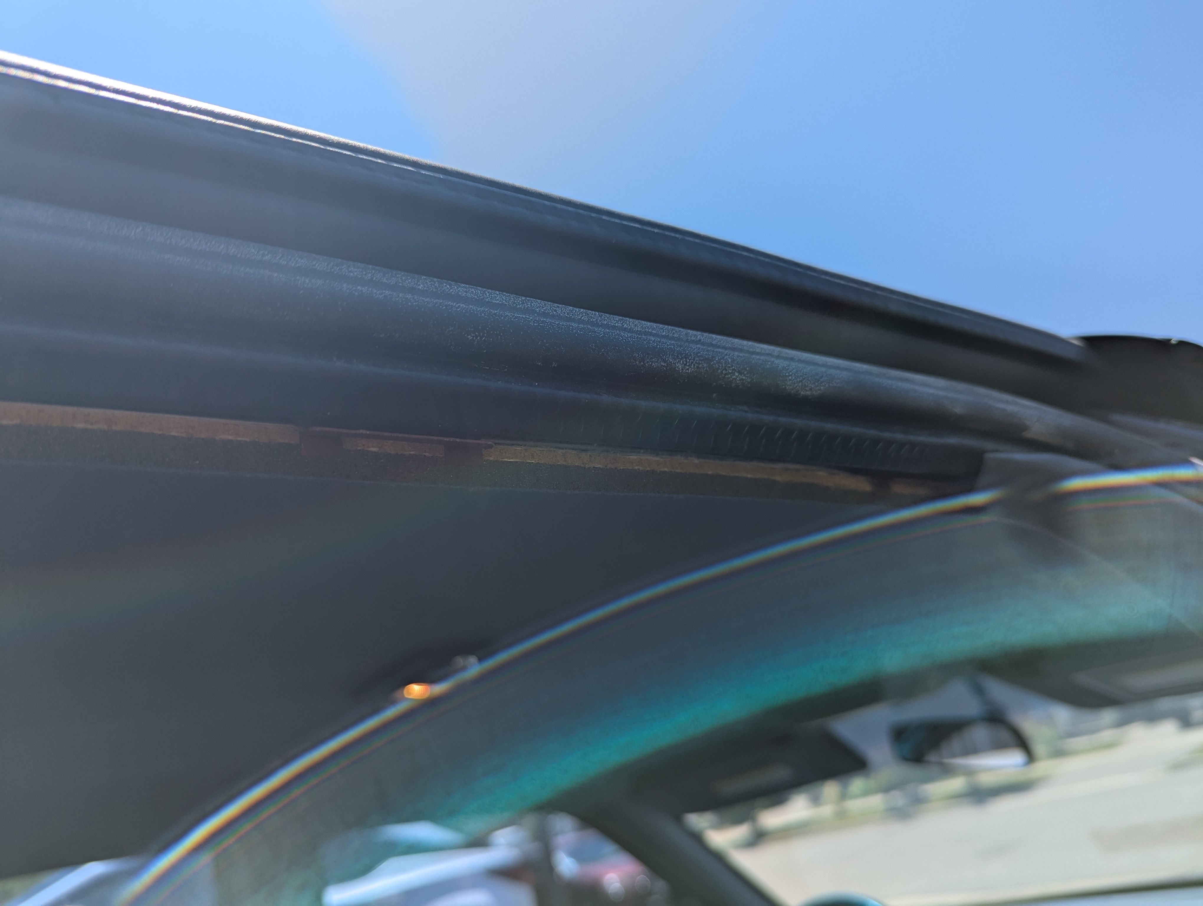
Yeah, I hate those one time use clips. I don't have the factory service manual, only parts catalogs, but there appear to be no fasteners for that part other than one staple (#3) towards the bottom. Not sure if that staple has to come out. It looks like the same annoying clip setup my Cutlass Supreme has along the top edge. If I recall the metal clip parts have sharp barbs and dig into the plastic, so some wear to the plastic happens every time you pull it. If the plastic tabs don't break off, they usually go back on and fit well enough, but it's not something you want to have to pull often. Looks like something near the top of the quarter glass and I'd guess that's an xmas tree type clip.
-
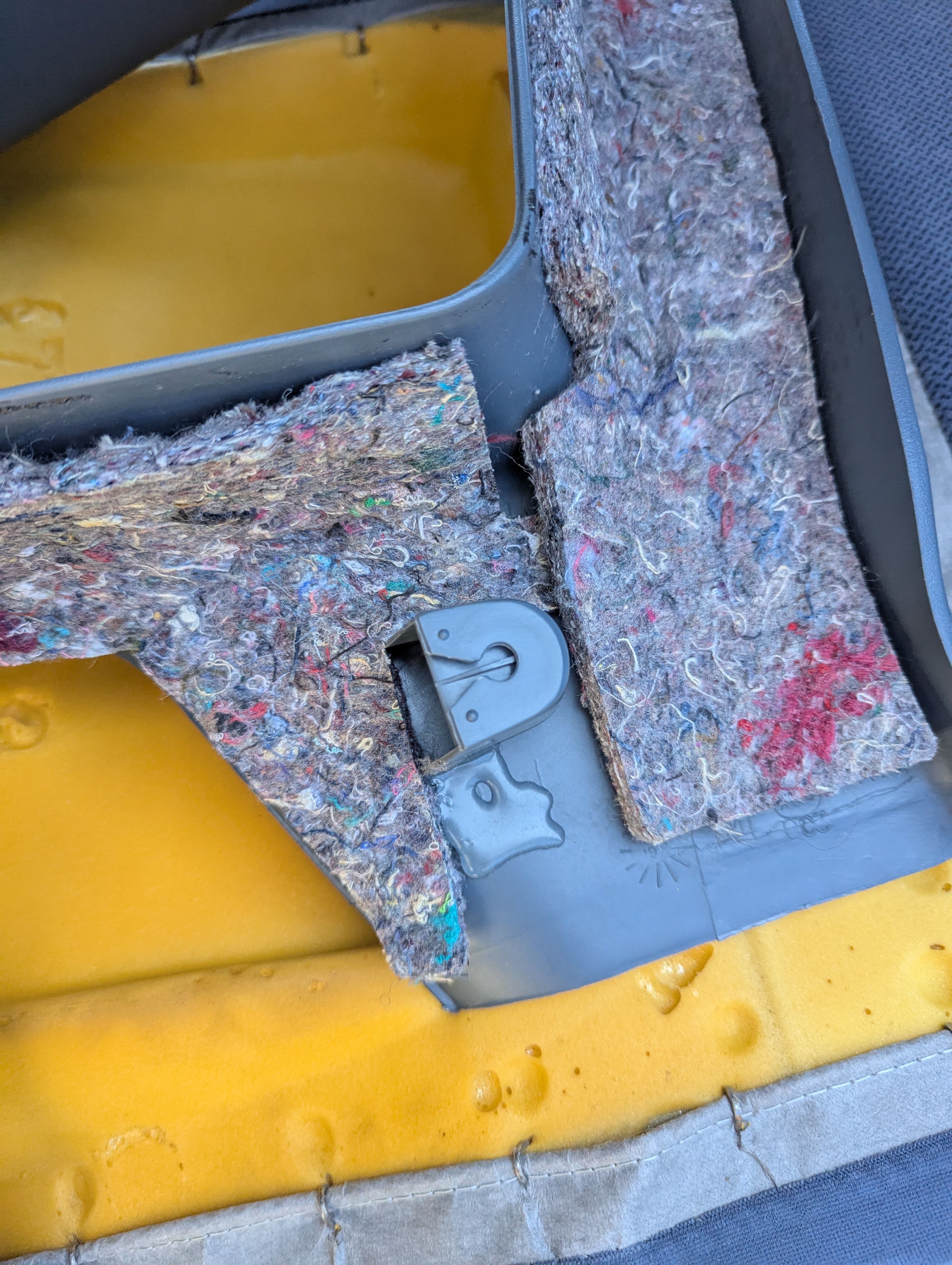
Thanks for the help. I got them off with a puller but couldn't do it without some damage. Hope they stay snug once I get 'em back in. I'm at the plastic trim around the glass now before I can lift the felt cover out. Any tricks with the trim? I don't see any fasenters so think I just need to pry off?
-
Unfortunately, they are indeed Xmas tree type. I used a standard trim panel puller to remove them. I was able to reuse mine after pulling, but it's possible they lost some strength after pulling.
-
Got the lower and upper seats off and see the plastic plugs holding down the upholdstery. Do I yank these out or is there a technique for 'em? Don't wanna ruin these! They appear to be the "xmas tree" style that goes in once. Not centre pinion to loosen or any form of spring action.
-
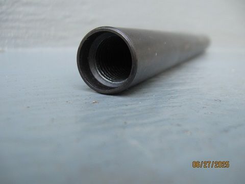
Need to know some info about replacing the strut cartridge?
ron350 replied to 89-W-Body-Regal's topic in Brakes/Suspension/Steering/Wheels/Tires
This tool acts as a handle that screws onto the threads on the end of the strut. Once installed you can move the strut around so you can center the strut in the hole. On my 96 the strut shaft wanted to move in the direction of the motor. I had to use pieces of wood wedged between the inner-fender and the strut spring to center the strut shaft so the removal tool would fit down the hole to the nut. Without this positioning tool i could not have changed my front struts. The guy in that video did not have this tool.
-
Need to know some info about replacing the strut cartridge?
ron350 replied to 89-W-Body-Regal's topic in Brakes/Suspension/Steering/Wheels/Tires
This tool in my kit was useless because it was too big to fit in the hole. Maybe this tool will work on your 98?