GM W-Body ECM Trouble Codes
What do you do when the Service Engine Soon light turns
on?
In every GM W-Body car, there is a computer
that controls virtually all aspects of the engine's operation. This computer
is called the ECM, or "Electronic Control Module". The ECM is constantly
controlling, adjusting, and monitoring engine conditions. If there is an engine
malfunction caused or detected by any one of the many sensors connected to the
ECM, a trouble code will be stored in NVM, or Non-Volatile Memory. What
you need to do first is find out what trouble codes are presently stored in
the ECM. You can read these trouble codes in several different ways. The best
and easiest way is to purchase a "scan tool". A scan tool displays trouble codes
numerically on a LCD display or computer terminal. The more expensive scan tools
also display the details behind the trouble code in full detail, such as the
sensor voltage detected and what it should be. The drawbacks to the scan tool
method is that a scan tool costs several thousands of dollars. The other method
is to perform a "NON-SCAN" diagnostic circuit check by having the "Service Engine
Soon" light blink out the codes stored in the ECM.
Regardless of the method used, the secret
to communicating with the car's computer is through the ALDL connector
(Assembly Line Diagnostic Link). This is where a scan tool would plug in. We
will also utilize this connector for our "NON-SCAN" method.
NOTE: The cheap $25-30 "scan tool" and
the $5 "scan key" that you find at many auto parts stores are NOT actual
scan tools. They are essentially expensive jumper wires. Don't buy them unless
you like wasting money, a paperclip or wire will work.
The following "NON-SCAN" method can
be used to read these codes.
A steady "Service Engine Soon" light
with ignition "ON" and engine stopped confirms battery and ignition voltage
to the ECM.
- First you must locate the ALDL connector
which is located under the dash on the driver's side, to the right of the
steering column.
The ALDL connector looks like this 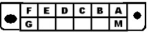
For reference, ALDL pinouts are:
A. Ground; B. Diagnostic Terminal; C. A.I.R. (if used); D. Service Engine
Soon Light (if used); E. Serial Data; F. TCC (if used); G. Fuel Pump (if used);
M. Serial Data (if used)
- Use a jumper (paper clip) and connect
terminal "B" to terminal "A". Terminal "A" is the ground connection. Turn
the ignition "ON", but don't start the engine, it must be left NOT RUNNING.
- The ECM will cause the "Service
Engine Soon" light to flash Code 12 three (3) times consecutively. This would
be the following flash sequence: "flash, pause, flash-flash, long pause,
flash, pause, flash-flash, long pause, flash, pause, flash-flash" (See
Figure 1). Code 12 means the diagnostic system is operating properly. Following
Code 12, the other trouble codes will be output if present, or Code 12 will
be output continuously if no other codes are stored. If more than one code
was stored, they will be output from lowest to highest, with each one being
displayed three times.
Example: An error Code 25 will be:
12,12,12,25,25,25,12,12,12, etc.

Figure 1: Example of "Service
Engine Soon" light flashing Code 12 continuously.
- To quit scanning for codes, simply
shut the ignition "OFF" and remove the jumper.
- To clear codes, ensure that the
ignition is "OFF". Depending on the car, you can disconnect an inline "pigtail"
fuse at the positive battery terminal, or remove the ECM fuse in the fuse
block. Power to the ECM must be disconnected for at least thirty (30) seconds.
This will cause the ECM to reset clearing all Codes, and the ECM will now
need to re-learn driving parameters.
The following chart gives Code # and
Description of the problem
Click on Malfunction Description
to get more detailed information.
CODE 12
Trouble Code 12 is a special-case code
that is not logged into the ECM's Non-Volatile Memory (NVM) when detected. When
the ECM detects no ignition reference pulses from the ignition module when the
ignition is in the 'ON' position, it illuminates the Check Engine Lamp (CEL),
but does not log this code as it would other codes.
Code 12 is used on most systems when
in the Diagnostic mode (ALDL Terminal B grounded, key-on/engine-off) to signal
the beginning or end of a so-called 'diagnostic sequence', when the ECM annunciates
each stored code in the ECM's NVM on the dash CEL.
When in this mode, the ECM will begin
by flashing code 12 on the CEL 3 times. This indicates the beginning of a diagnostic
sequence. It will then flash any codes stored in NVM 3 times each before proceeding
to the next code. When all stored codes are finished, the ECM will again flash
code 12 to indicate the end of the diagnostic sequence. The cycle will continue
as long as the ECM is in Diagnostic Mode.
NOTE: Codes are not displayed in order
of occurance but rather in numerical order.
Return to Chart
CODE 13
Trouble Code 13 indicates that the exhaust
stream oxygen-content sensor (O2 sensor) is not responding as expected. When
cold, the sensor is 'biased' by the ECM to about 450 millivolts. Before it warms
to at least 600 deg F (315 deg C) it acts as an open circuit and when the ECM
reads it, it reads the 450 mV bias. The ECM expects the sensor to warm in a
short period of time and begin sending its own voltages. The general conditions
for this code getting set are:
- engine running at least 2 minutes
- coolant temperature at least 50
deg C (122 deg F)
- O2 voltage not fluctuating (i.e
steady between 350 and 550 mV)
- TPS signal above idle
- all above conditions met for 60
seconds
Typical causes may include:
- Defective or degraded O2 sensor
- Deposit-contaminated O2 sensor (running
leaded fuel, RTV silicone deposits etc)
- Corroded/defective O2 sensor connection
- Defective sensor ground circuit
- Defective connection at ECM
- Defective ECM
NOTE: If codes 21 and/or 22 are also present
cause '4' above should be checked first.
Return to Chart
CODE 14
Trouble Code 14 indicates that the Coolant
Temperature Sensor (CTS) is reporting abnormally high readings. CTS is used
to control fuel mixture, timing, idle speed, TCC and EGR operations among others.
The thermistor used has a high-resistance when cold, lowering as the coolant
warms.
Code 14 will set if:
- temperature reported is > 270 deg
F (135 deg C)
- conditions above are present for
more than 20 seconds
Typical thermistor resistances expected
are:
| Deg C |
Deg F |
Resistance (ohms) |
| 100 |
212 |
177 |
| 70 |
158 |
332 |
| 40 |
104 |
1459 |
| 20 |
68 |
3520 |
| 5 |
41 |
7280 |
| -5 |
23 |
12300 |
| -20 |
-4 |
28680 |
| -40 |
-40 |
100700 |
Typical causes may include:
- Severe engine overheating
- Defective Coolant Temperature Sensor
- Short circuit in CTS-ECM harness
- Defective ECM
Return to Chart
CODE 15
Trouble Code 15 indicates that the Coolant
Temperature Sensor (CTS) is reporting abnormally low readings. CTS is used to
control fuel mixture, timing, idle speed, TCC and EGR operation, among others.
The thermistor used has a high-resistance when cold, lowering as the coolant
warms.
Code 15 will set if:
- temperature reported is < -37.30
deg F (-38.5 deg C)
Typical thermistor resistances expected
are:
| Deg C |
Deg F |
Resistance (ohms) |
| 100 |
212 |
177 |
| 70 |
158 |
332 |
| 40 |
104 |
1459 |
| 20 |
68 |
3520 |
| 5 |
41 |
7280 |
| -5 |
23 |
12300 |
| -20 |
-4 |
28680 |
| -40 |
-40 |
100700 |
Typical causes may include:
- Open circuit in CTS-ECM harness
- Defective Coolant Temperature Sensor
- Open sensor ground circuit
- Defective ECM
Return to Chart
CODE 21
Trouble Code 21 indicates that the Throttle
Position Sensor (TPS) is reading abnormally high. TPS volts should be close
to 0.42 V at closed throttle and rise smoothly in about 0.02 volt increments
to a maximum reading of about 4.85 volts at WOT.
Code 21 will set if:
- Engine is running
- TPS signal voltage is greater than
4.3 volts
- No Code 33 or Code 34
- Air Flow is less than 17 gm/sec.
- All conditions met for 1.25 seconds
Typical causes for this code include:
- Defective TPS
- Short circuit in the TPS harness
to +5 volt reference
- Open sensor ground circuit
- Defective ECM
NOTE: Presence of codes 33 and/or 34 may
indicate that the MAP sensor is defective and is reading less than expected. This
may cause the above set-conditions to be met falsely and this code to be set.
Return to Chart
CODE 22
Trouble Code 22 indicates that the Throttle
Position Sensor (TPS) is reading abnormally low. TPS volts should be close to
0.42 V at closed throttle and rise smoothly in about 0.02 volt increments to
a maximum reading of about 4.85 volts at WOT.
Code 22 will set if:
- Engine Running
- TPS reading < 0.25 volts for
3 seconds
Typical causes for this code include:
- Circuit Open or Shorted to Ground
- Faulty Connection
- Faulty TPS
- Defective ECM
TPS cannot be adjusted, the TPS has an
auto zeroing feature.
Return to Chart
CODE 23
Trouble Code 23 indicates that the Manifold
Air Temperature (MAT) sensor or Intake Air Temperature (IAT) is reading lower
than expected. When the air is cold, the thermistor has a high resistance, which
falls as the air charge warms. Low readings thus indicate possible open circuits
in MAT circuit.
Code 23 will set if:
- MAT reading is < -31 deg F (-35
deg C)
- Time since engine start is 4 minutes
or longer.
- Vehicle speed less than 1 mph
- Start-up coolant temperature is
less than or equal to -35.5 C (31.9 F).
- All conditions met for 10 sec.
Typical causes for this code include:
- Defective MAT or IAT sensor
- Open sensor ground circuit
- Dirty or corroded connection(s)
at MAT/IAT and/or ECM
- Open circuit between the ECM and
the MAT/IAT sensor
- Defective ECM
Return to Chart
CODE 24
Trouble Code 24 indicates that the Vehicle
Speed Sensor (VSS) is not sending the expected (based on other system parameters
like LV8, TPS, RPM etc.) signal to the ECM.
Code 24 will be set if vehicle speed
equals zero 0 mph when:
- VSS indicates less than 2mph.
- MAP is less than 30 kPa.
- Engine speed is between 2200 and
4400 RPM
- TPS is less than 2%.
- Not in Park or Neutral
- No Code 21, 22, 33, or 34.
- All conditions met for 3 seconds
If the code was logged when the vehicle
was in motion, the following should be checked:
- VSS circuit open, shorted to ground,
shorted together
- Faulty Connections
- Defective VSS
- Defective ECM
- A faulty or misadjusted Park/Neutral
(P/N) switch can result in false Code 24.
Return to Chart
CODE 25
Trouble Code 25 indicates that the Manifold
Air Temperature (MAT) or Intake Air Temperature (IAT) sensor is reading higher
than expected. When the air is cold, the thermistor has a high resistance, which
falls as the air charge warms. High readings thus indicate possible short circuits
in MAT circuit.
Code 25 will set if:
- MAT/IAT reading is > 293 deg F (135
deg C) for .2 seconds
- vehicle speed is greater than 1
MPH
Typical causes for this code include:
- Defective MAT/IAT sensor
- MAT/IAT signal shorted to ground
or to sensor ground
- Defective ECM
Return to Chart
CODE 26
Trouble Code 26 indicates that the quad-driver
is malfunctioning.
QDM symptoms:
- Cooling fan(s) inoperative
- Poor driveability due to 100% canister
purge.
- Coolant light "ON" all the time,
"OFF" during bulb check.
- EGR inoperative - Code 32.
- TCC inoperative
This problem can be caused by:
- Short to 12 volts on the control
circuit by a shorted component.
- Faulty ECM.
Return to Chart
CODE 32
Trouble Code 32 indicates that the Exhaust
Gas Recirculation (EGR) system has detected a fault. There are two types, the
older integrated electronic EGR contains a voltage regulator which converts
the ECM signal to provide different amounts of EGR flow by regulating the current
to the solenoid. The ECM controls EGR flow with a pulse width modulated signal
(turns "ON" and "OFF" many times a second) based on airflow, TPS, and RPM. This
system also contains a pintle position sensor which works similar to a TPS sensor,
and as EGR flow is increased, the sensor output also increases. The other type
is a digital 3-level EGR used in newer engines. Code 32 will get set when:
- (Integrated EGR) Coolant temperature
above the specified amount, EGR should be on.
- (Integrated EGR) EGR pintle position
does not match duty cycle.
- (Digital EGR) Failure of EGR system.
Possible causes include:
- Faulty EGR valve-to-ECM connection
- Plugged EGR passages and/or sticking
EGR valve
- Defective EGR valve
- Defective ECM
Check the shop manual for details on vehicle
specific EGR valve applications.
Return to Chart
CODE 33
Trouble Code 33 indicates that the Manifold
Absolute Pressure (MAP) sensor is detecting unusually low vacuum in the manifold.
Code 33 will get set when:
- No Code 21 or Code 22.
- Engine running.
- Manifold pressure greater than 74
kPa (A/C "OFF") 83.4 kPa (A/C "ON.")
- Throttle angle less than 2%.
- Conditions met for 4.8 seconds.
Possible causes include:
- Faulty MAP-to-ECM connection
- Plugged or leaking sensor vacuum
hose
- Defective MAP sensor
- Defective ECM
Check the shop manual for details on vehicle
specific MAP sensor applications.
Return to Chart
CODE 34
Trouble Code 34 indicates that the Manifold
Absolute Pressure (MAP) sensor is detecting unusually high vacuum in the manifold.
Code 34 will get set when:
- Engine RPM less than 700.
- Manifold pressure reading less than
13 kPa.
- Conditions met for .22 second.
OR
- Engine RPM greater than 700.
- Throttle angle over 20%.
- Manifold pressure less than 13 kPa.
- Conditions met for .22 second.
Possible causes include:
- Faulty MAP-to-ECM connection
- Defective MAP sensor
- Defective ECM
Check the shop manual for details on vehicle
specific MAP sensor applications.
Return to Chart
CODE 35
Trouble Code 35 indicates a problem
with the Idle Speed Control (ISC) circuit. It will be set when the closed throttle
engine speed is 200 RPM above or below the desired (commanded) idle speed for
50 seconds. Possible causes include:
- Vacuum Leak (High Idle) - Also check
for binding of throttle blade or linkage.
- System too lean (High Air/Fuel Ratio)
- The idle speed may be too high or too low. Check for low regulated fuel
pressure, water in the fuel, or a restricted injector.
- System too rich (Low Air/Fuel Ratio)
- The idle speed will be too low. May exhibit black smoke in exhaust. Check
for high fuel pressure, leaking or sticking injector.
- Foreign material in throttle body.
- Faulty IAC Valve electrical connections.
- Faulty PCV valve.
- Faulty IAC.
- Faulty ECM.
Return to Chart
CODE 41
Trouble Code 41 indicates an incorrect
MEM-CAL has been installed or it is faulty and it must be replaced.
Possible causes include:
- Faulty connection due to MEM-CAL
not locked in place.
- Incorrect MEM-CAL installed.
- Faulty MEM-CAL.
Return to Chart
CODE 42
Trouble Code 42 indicates that there
may be a malfunction in the Electronic Spark Timing (EST) system. During cranking,
the timing is controlled by the ignition module and the ECM grounds the EST
line. It expects to see no activity on this line at this time. When the ECM
enters EST mode, it applies +5 volts to the BYPASS line and expects to see voltage
variations on the EST line.
Reasons for the ECM to set Code 42:
- System in BYPASS mode (i.e. EST
line supposedly grounded) but activity sensed on EST line
- System in EST mode (i.e. BYPASS
line driven with +5 volts) but no activity seen on the EST line
Possible causes include:
- BYPASS line is open or grounded
- EST line is open or grounded
- Poor connections between ignition
module and ECM
- Poor routing of EST harness and/or
poor quality ignition wires (EMI induced electrical noise
- Faulty or incorrect ignition module
- Faulty ECM
Return to Chart
CODE 43
Trouble Code 43 indicates that there
may be a malfunction in the Electronic Spark Control (ESC) circuit. ESC is used
to sense spark knock (pinging) and retard the timing to eliminate it. The knock
sensor is located at the rear of the engine block. The ECM will retard the timing
by as much as 20 degrees in 1 degree increments. A loss of knock sensor signal
or loss of ground at the ESC module will cause the signal at the ECM to remain
high. The ECM will act as if no knock is present, and may possibly result in
engine damage, due to detonation.
Code 43 is set when:
- Voltage at Knock Sensor is above
4.8 volts or below .64 volts.
- Either condition is met for about
10 seconds.
Possible causes:
- Open or shorted knock sensor
- Loose knock sensor
- Excessive mechanical noise within
engine
- Improper or incorrectly installed
MEM-CAL in the ECM or defective ECM
- Intermittent open in the EST line
to the ignition module
Return to Chart
CODE 44
Trouble Code 44 indicates that the O2
sensor is showing a persistently high exhaust oxygen content (lean), despite
the efforts of the ECM to increase injector on-time (thus increasing fuel delivered).
Integrator and BLM numbers may indicate > 128 by a substantial margin.
Code 44 is set when:
- O2 sensor voltage remains below
.2 volt for 60 or more seconds
- System is operating in "Closed Loop."
- No Code 33 or Code 34
Possible causes include:
- O2 sensor defective or lead shorted
- Lean injectors (dirty or blocked)
- Water in fuel
- Exhaust leaks upstream of O2 sensor
- Fuel pressure too low
Note: Presence of Code(s) 33 and/or 34
may indicate MAP problem. This should be the first suspect in the case of a Code
44 being set.
Return to Chart
CODE 45
Trouble Code 45 indicates that the O2
sensor is showing a persistently low exhaust oxygen content (rich), despite
the efforts of the ECM to decrease injector on-time (thus decreasing fuel delivered).
Integrator and BLM numbers may indicate < 128 by a substantial margin.
Code 45 is set when:
- O2 sensor voltage remains above
.7 volt for 50 seconds
- engine has been running for 1 minute
or more
- throttle is between 3 and 45 percent
open
- system is running "Closed Loop"
Possible causes include:
- O2 sensor defective or contaminated
(if incorrect RTV sealant or too much RTV is used, this may happen)
- Leaking fuel injectors
- Fuel pressure too high
- EMI interference from poor plug
wires
- Evaporative Emission system defect
- TPS and/or EGR problem
Note: Presence of Code(s) 33 and/or 34
may indicate MAP problem. This should be the first suspect in the case of a Code
45 being set.
Return to Chart
CODE 51
Trouble Code 51 indicates that the ECM
sensed a fault in the MEM-CAL. On power-up, the ECM does a checksum of the MEM-CAL
to ensure the MEM-CAL integrity is good. If the calculated sum does not match
the sum in the MEM-CAL, the ECM will hardcode 51 and enter Back-Up mode, since
the ECM cannot know where in the MEM-CAL the fault lies.
Code 51 is set when:
- the actual MEM-CAL checksum does
not match the value in the MEM-CAL
Possible causes include:
- Incorrectly installed MEM-CAL module
- Defective MEM-CAL module
- Defective ECM
Return to Chart
CODE 52
Trouble Code 52 indicates that the ECM
sensed a fault in the CALPACK. The CALPACK is a module separate from the PROM
that contains preset calibrations used by the system in the limp-home mode.
The ECM checks for its presence at power up.
Code 52 gets set when:
- the ECM does not sense the CALPACK
Possible causes include:
- Incorrectly installed CALPACK module
- Incorrect CALPACK module for this
vehicle
- Defective or incorrectly inserted
PROM
- Defective ECM
Return to Chart
CODE 53
This code will be set when the ignition
is "ON", and the engine RPM is greater than 800 and the ECM is seeing a ignition
fuel reference voltage of more than 17.1 volts. During the time of this failure,
all ECM outputs will be disengaged.
Possible causes include:
- Faulty generator.
- Faulty ECM.
Return to Chart
CODE 54
Trouble Code 54 indicates a low voltage
at the fuel pump. If the voltage at terminal "A20" is less than 4 volts for
.4 seconds since the last reference pulse was received, the code will be set.
Possible causes include:
- Faulty fuel pump relay.
- Faulty connection at ECM.
- Faulty oil pressure switch.
- Faulty ECM.
Return to Chart
CODE 55
Trouble Code 55 indicates that the Analog-
to-Digital (A/D) converter in the ECM timed out. The ECM checks this by initiating
a conversion and timing how long it takes to complete. If the converter, for
whatever reason, fails to signal the End-Of-Conversion (EOC) before a timeout
counter runs down, the ECM assumes it is bad and sets this code.
Possible causes for Code 55 are limited
to:
- Defective or incorrectly inserted
MEM-CAL
- Defective ECM
If replacing the ECM, be sure to transfer
both the PROM and the CALPACK from the old unit. If the old-ECM also indicated
PROM failure (Code 51) or a bad CALPACK (Code 52), be sure to verify these components
are fully operational in the new unit. If they are not, they too will have to
be replaced.
Return to Chart
CODE 61
Trouble Code 61 indicates that the ECM
has determined the oxygen sensor is contaminated or degraded, because the voltage
change time is slow or sluggish.
Possible causes:
- Contaminated Oxygen sensor.
- Oxygen sensor needs replacement.
Return to Chart
CODE 66
Trouble Code 66 indicates that A/C pressure
sensor has determined that the A/C refrigerant system pressure is either too
low (0 psi, .1 volt at sensor) or too high (450 PSI, 4.6 volts at sensor) for
5 seconds or more. If this code is present, the A/C compressor is disabled by
the ECM.
Possible causes:
- A/C system pressure is above or
below calibrated values.
- Faulty A/C Pressure Sensor or wiring.
- Faulty ECM.
Return to Chart